SRS - Cable Harness Repair/Replacement: Overview
CarsS40 (-04)/V40
2000-
Section:
8
Group:
88
No.:
0030
Year:
04
Month:
04
Miscellaneous:
Competence requirement: Volvo Level 2 Technician
SRS Cable Harness, Replacing and Repairing Cable Harnesses Based on SRS Diagnostic Trouble Codes (DTCs)
Background:
This Service Bulletin describes repair methods for various SRS cable harnesses. The described repairs should only be performed after the proper fault tracing has indicated a fault with the wire harness.

Affected cars
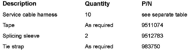
Material
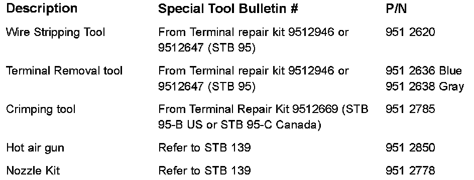
Special tool
Contents:
A: General
B: Installing the service cable harnesses
C: Replacing the terminals in the connector for the supplemental restraint system control module (SRS)
D: Repairing SRS wiring
E: Final check
General information
A fault in the SRS (supplemental restraint system) may be caused by faults in the wiring. Examples of this are:
^ All diagnostic trouble codes (DTCs) with the description "high resistance". Possible cause: loose connections in a connector.
^ All diagnostic trouble codes (DTCs) with the description "low resistance". Possible causes: short-circuit (damage) to the wiring, poorly connected or damaged connector.
^ All diagnostic trouble codes (DTCs) with the description "high voltage". Possible cause: short-circuit (damage) in the wiring.
Note!
The possible causes of these faults are always listed in the description of SRS diagnostic trouble codes (DTCs) in VADIS. References are often given to cables.
It is not necessary to replace the entire existing cable harness. The fault can be remedied by replacing only the faulty cables.
This can be done in two different ways:
1 By using service cable harnesses, according to method B.
2 By using a section of the service cable harness, see method D.
Note!
If there is physical damage to the SRS wiring or the connectors between the Supplemental Restraint System control module (SRS) and one of the SRS components (except for the drivers and passengers airbag) the damaged part of the cables can be replaced instead of the entire service cable harness.
In method D there is a description of how to splice cables using splicing sleeves P/N 951 2783.
Note!
The damaged part including the connector must always be replaced between two connections. Do not repair the cable between two connections.
Note!
The ignitor connector has changed color. It is now yellow.
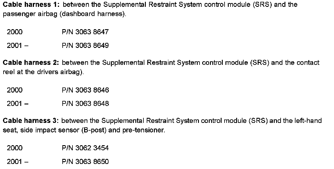
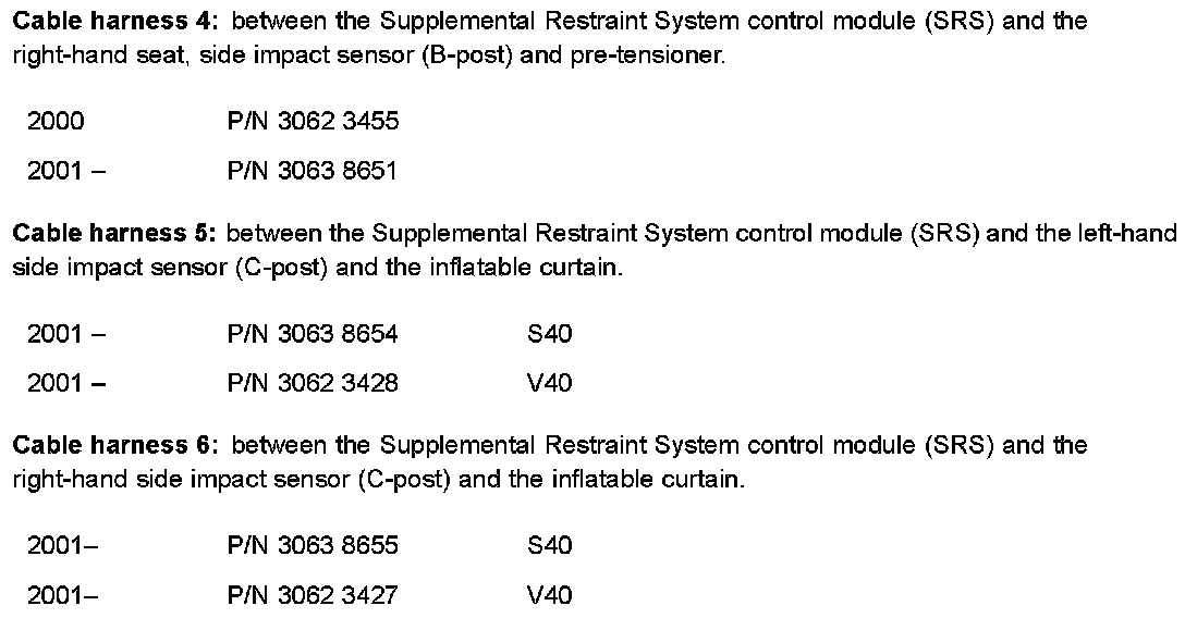
Service cable harness, part numbers shown.
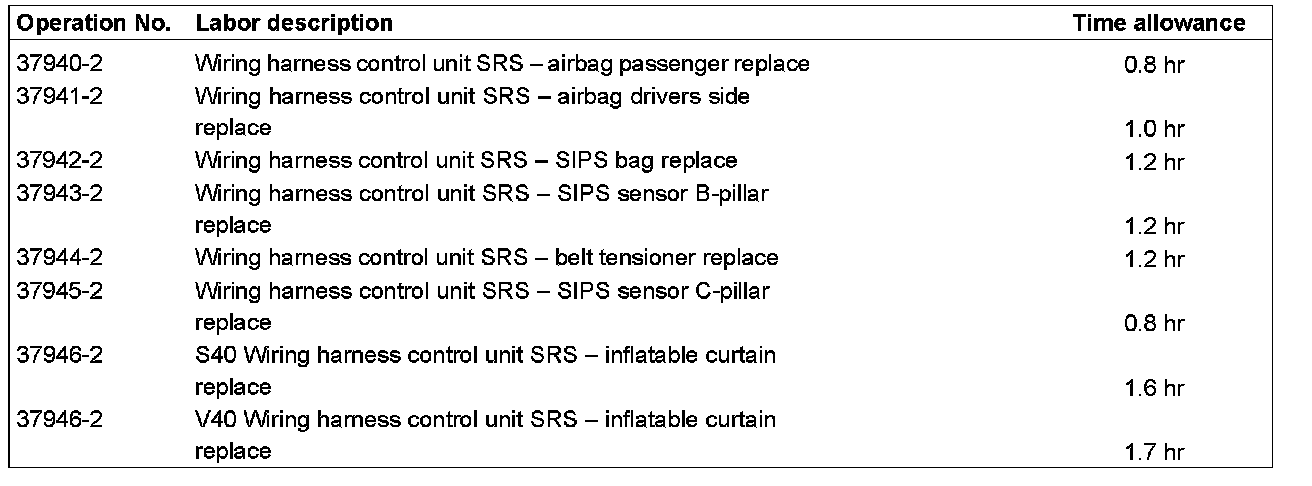
WARRANTY STATEMENT:
Claims may be submitted under the New Car Warranty when there is a documented customer complaint, using claim type 01.