Electric Cooling Fan Diagnosis
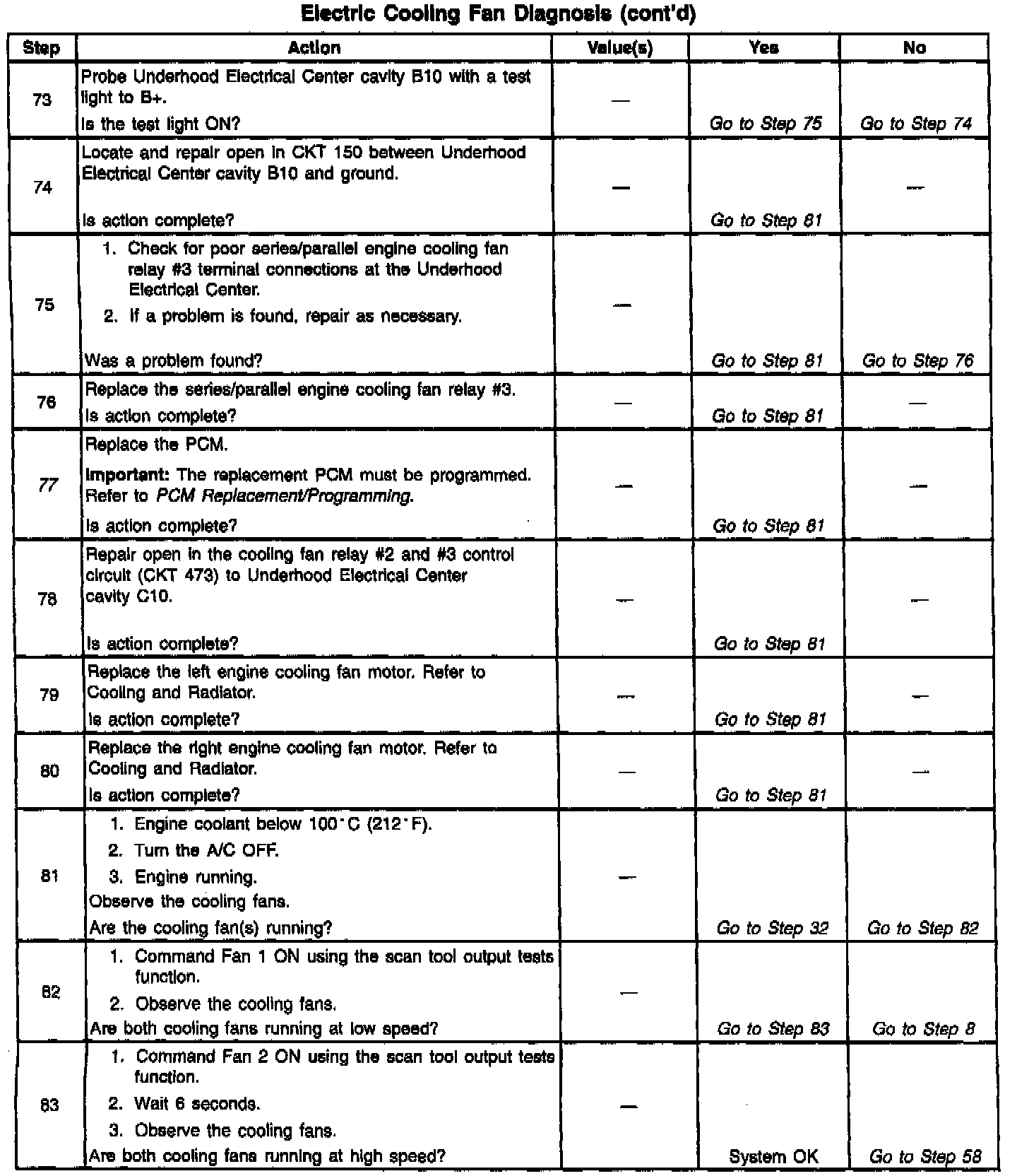
Diagnostic Chart:
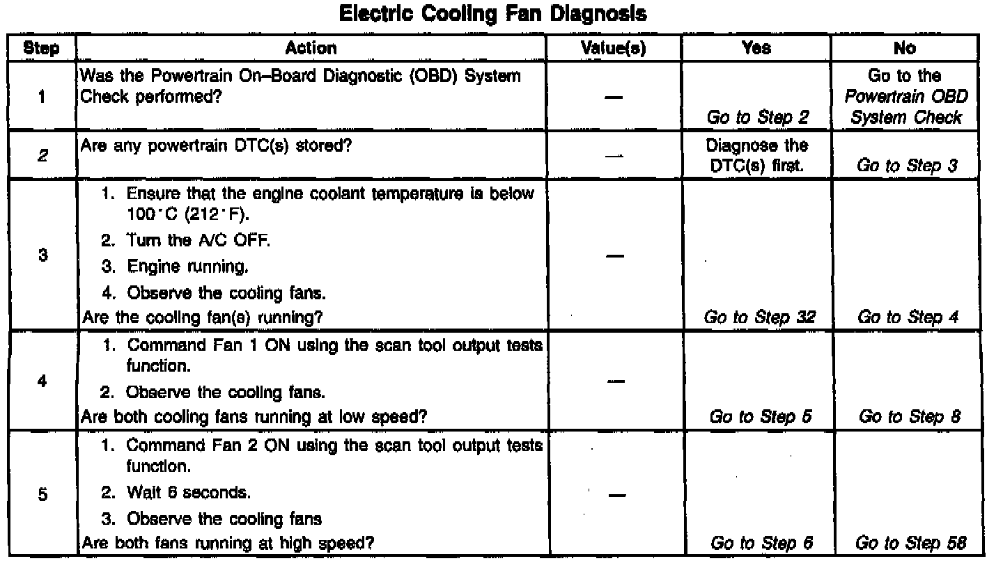
Diagnostic Chart:
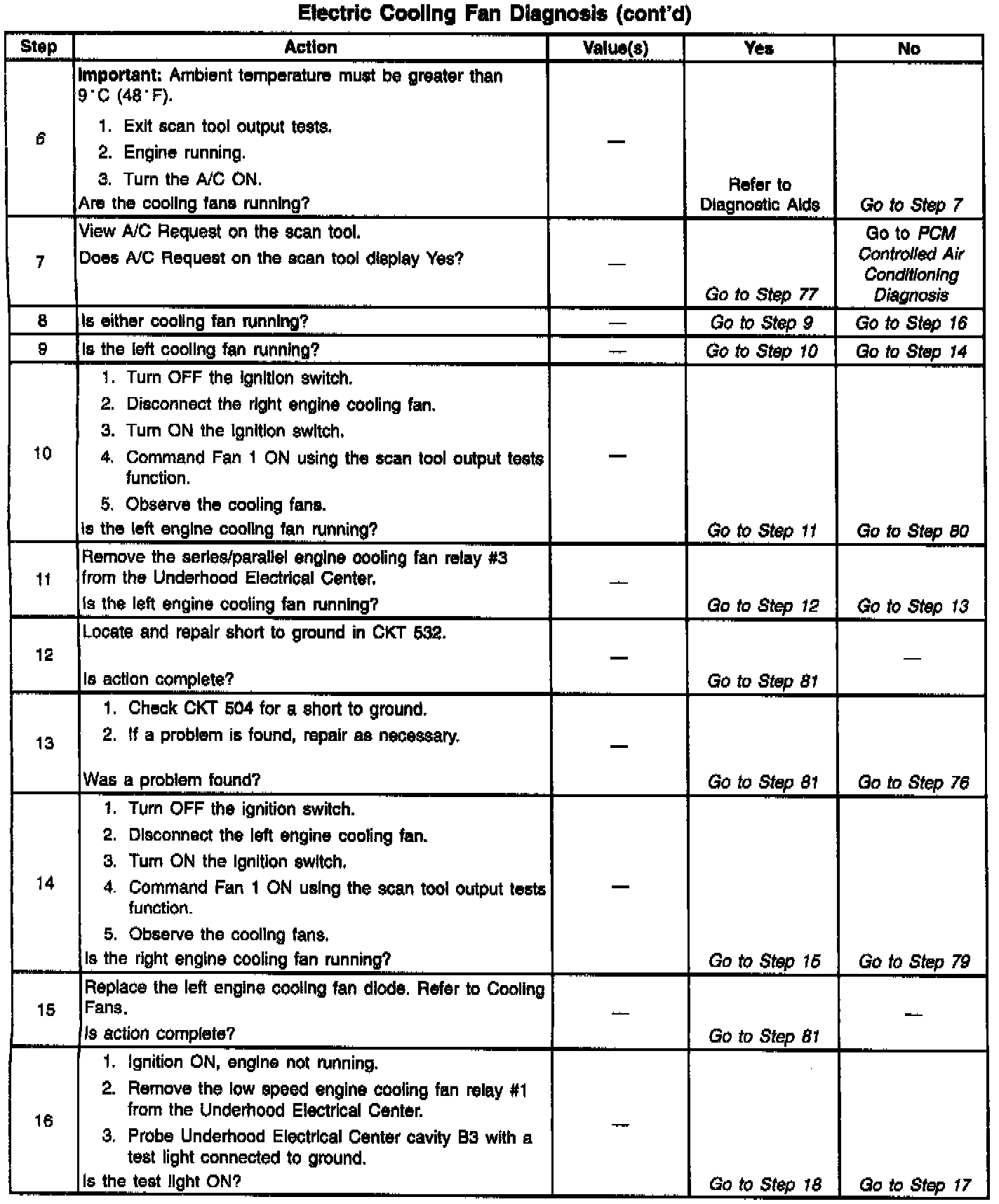
Diagnostic Chart:
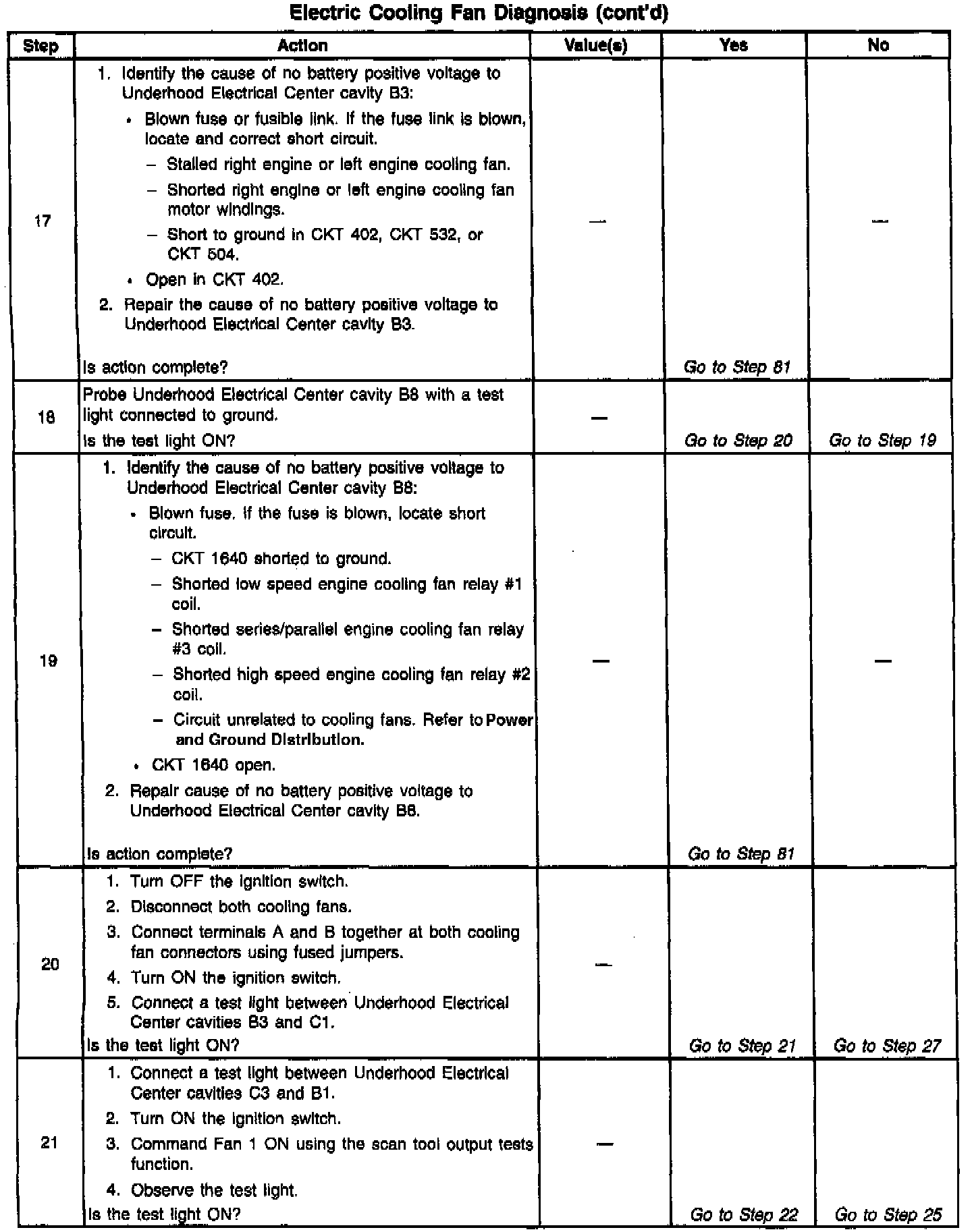
Diagnostic Chart:
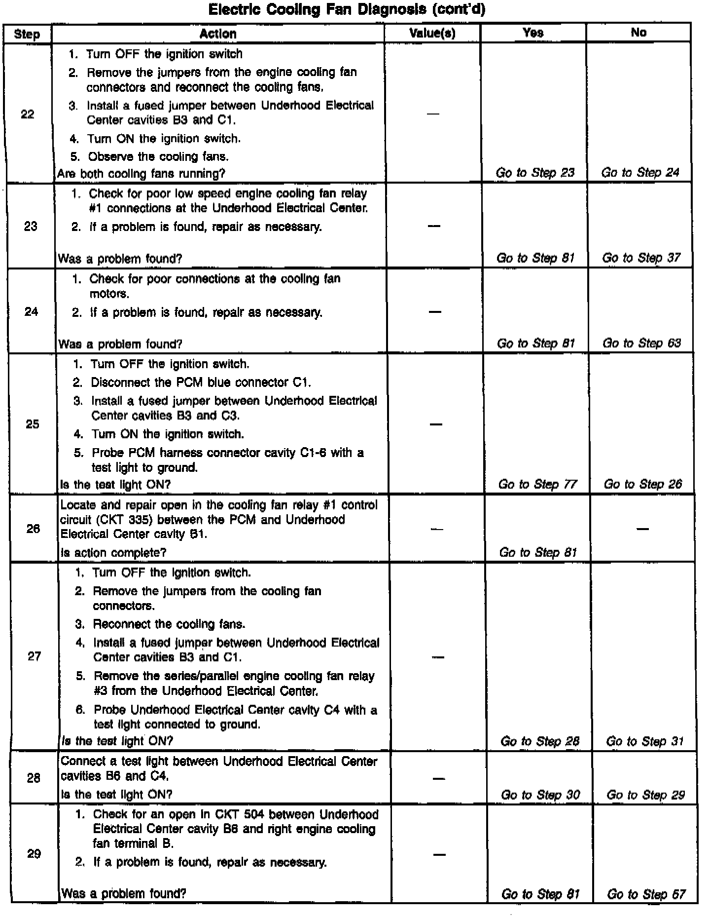
Diagnostic Chart:
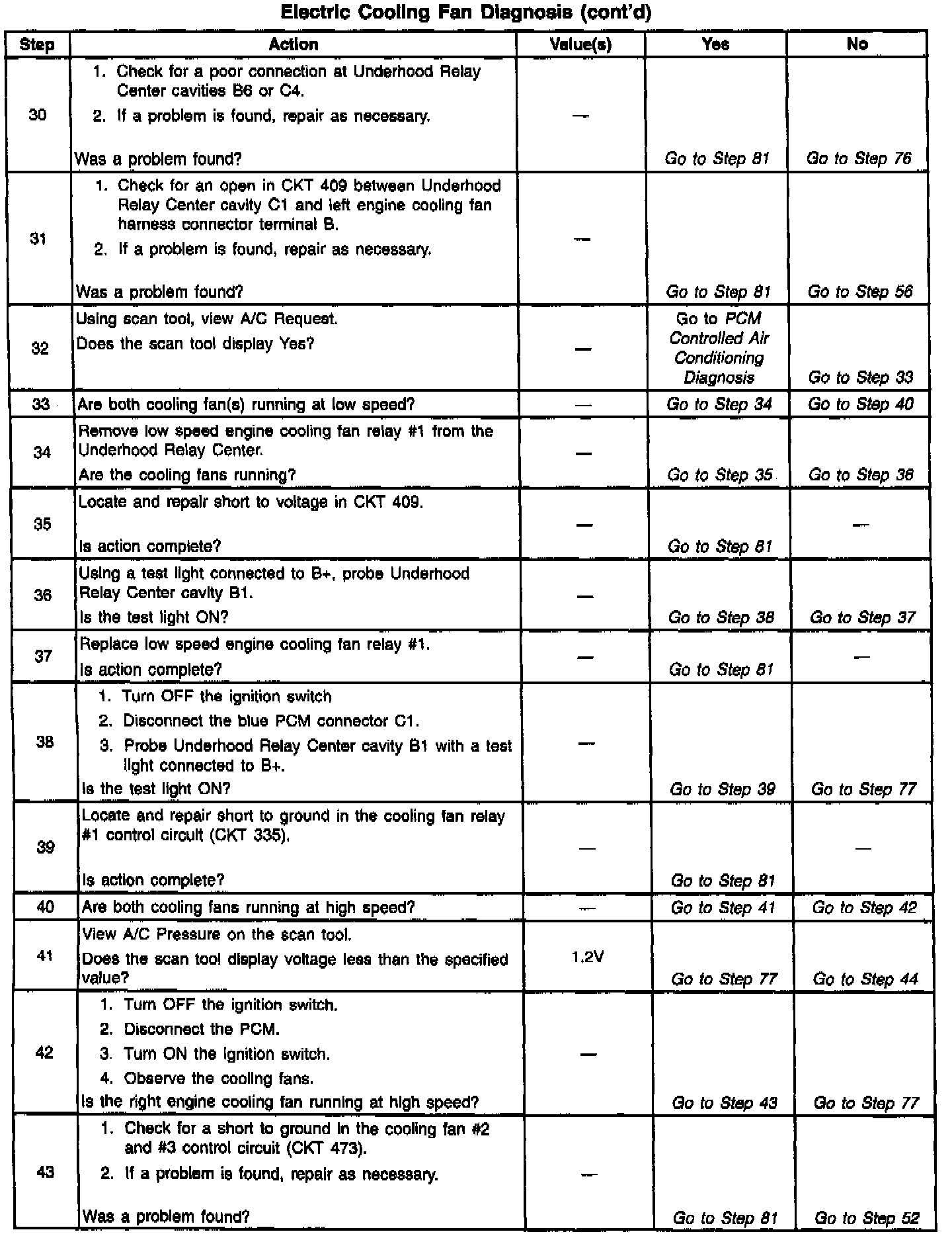
Diagnostic Chart:
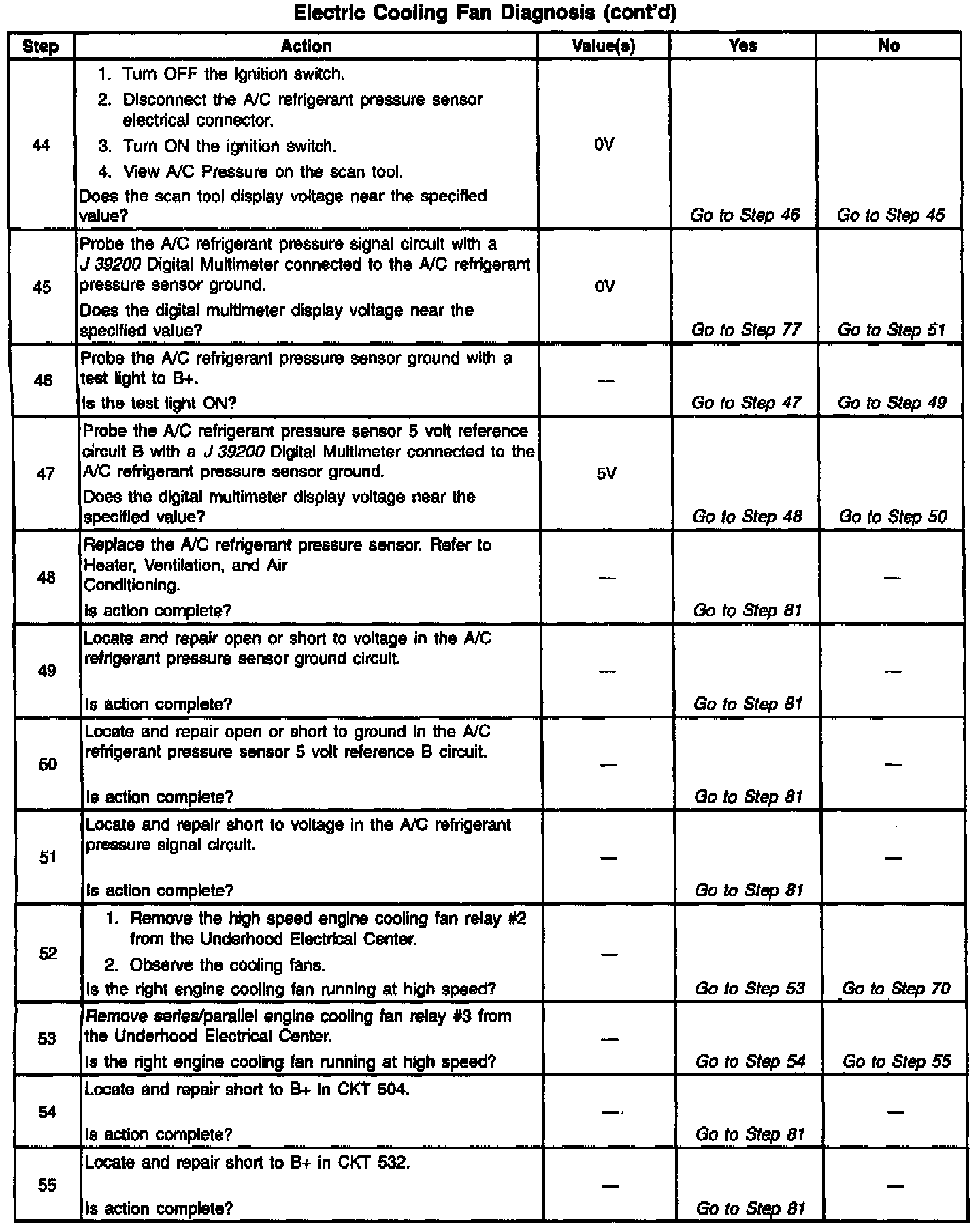
Diagnostic Chart:
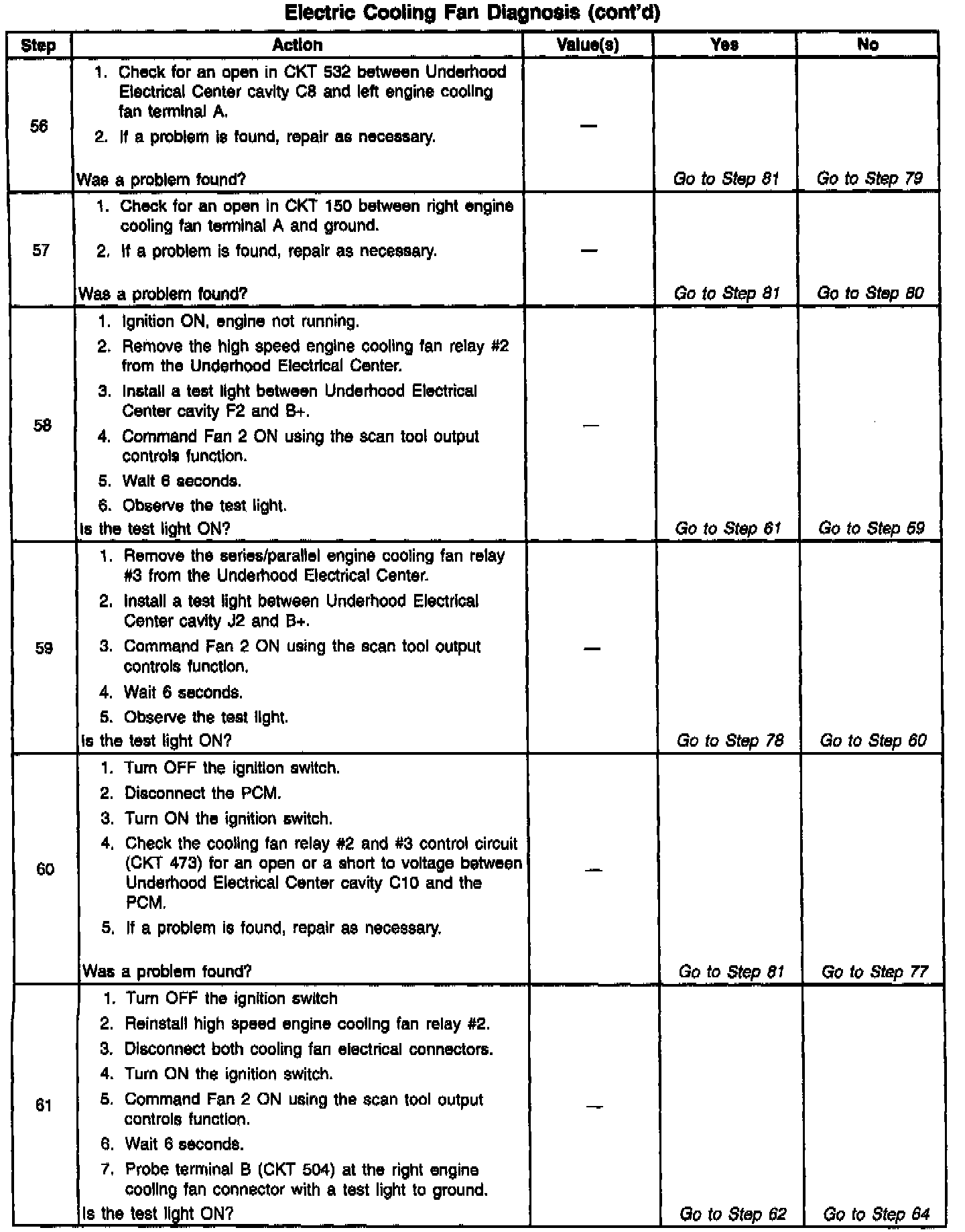
Diagnostic Chart:
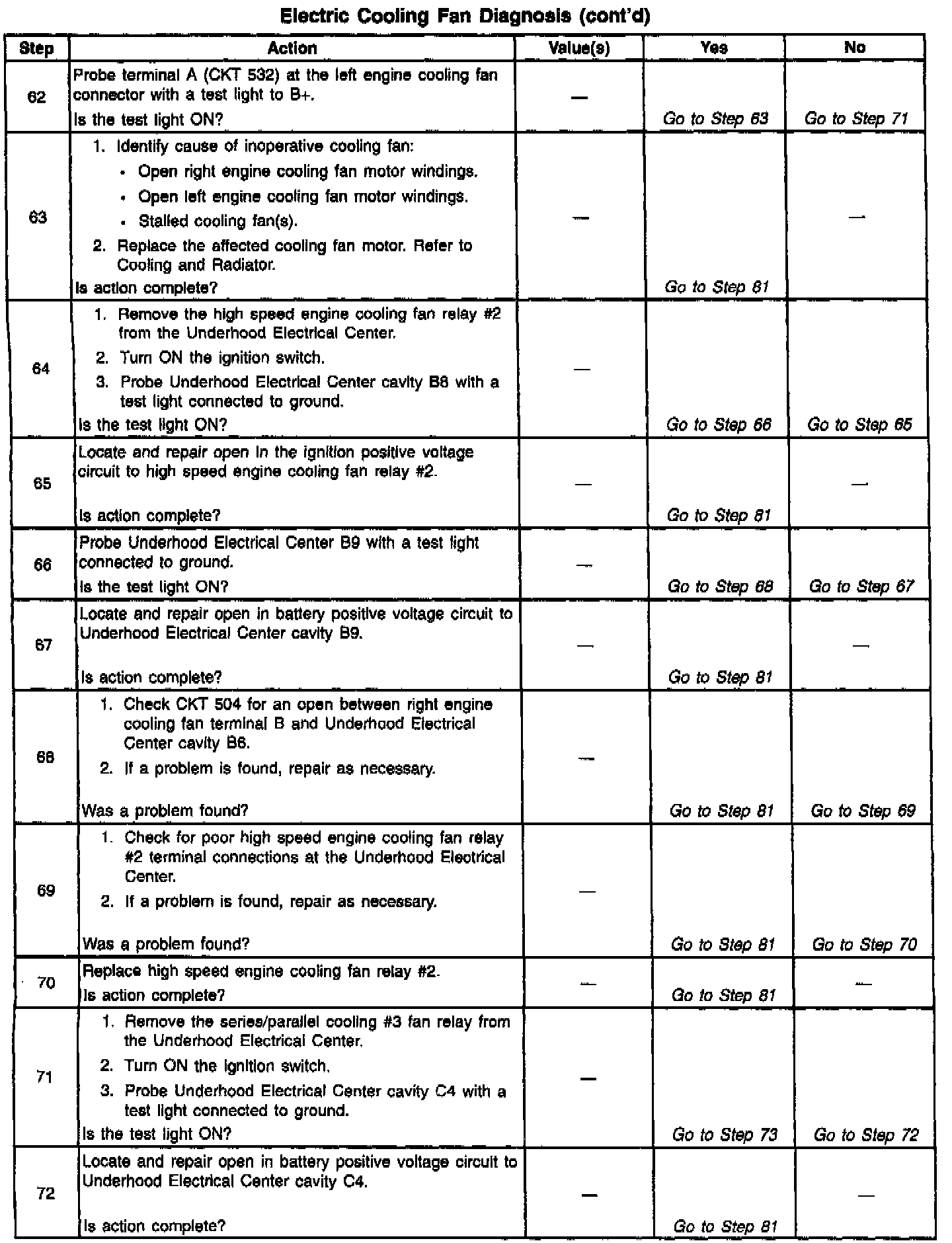
Diagnostic Chart:
Wiring Diagram:
CIRCUIT DESCRIPTION:
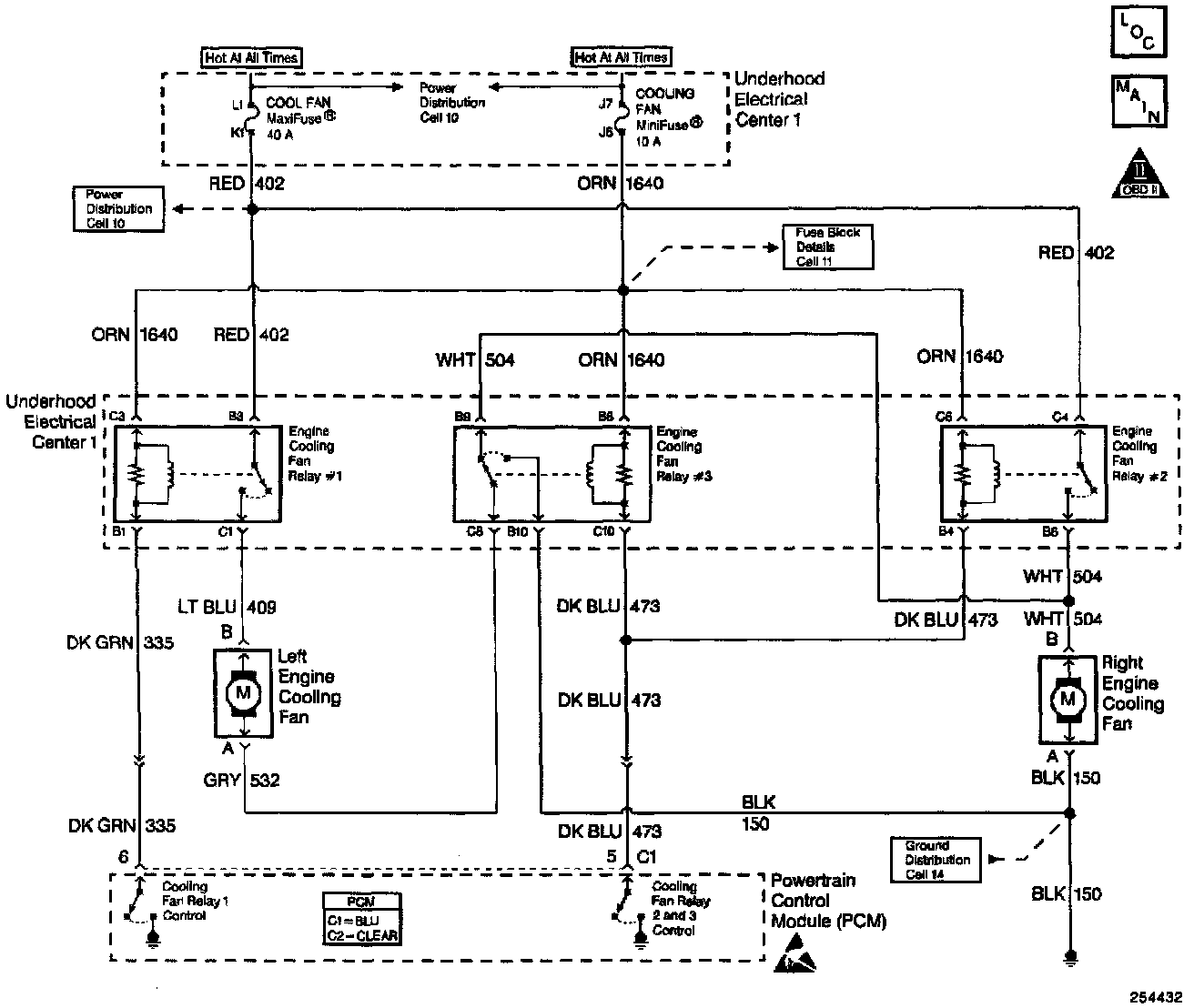
Power for the fan motors is supplied through a 40 amp MaxiFuse� located in the Underhood Fuse Block. The cooling fan relays receive power from a 25 amp fuse located in the Underhood Fuse Block.
During low speed fans operation the PCM supplies a ground path for the engine cooling fan relay #1. This closes the engine cooling fan relay #1 contacts, allowing current to flow from the 40 amp Maxifuse�, through the relay contacts, and to the left engine cooling fan. During low speed operation, the ground path for the left cooling fan is through the engine cooling fan relay #3 and the right engine cooling fan motor. The result is a series circuit with both cooling fans running at low speed.
During high speed cooling fan operation, the PCM supplies a ground path for the engine cooling fan relay #1. After a 6 second delay, the PCM supplies a ground path for engine cooling fan relay #2 and engine cooling fan relay #3. The 6 second delay ensures that the cooling fan electrical load will not exceed the capacity of the system. During high speed fans operation, both the engine cooling fans are supplied current from the 40 amp Maxifuse� and each cooling fan has its own ground path.
DIAGNOSTIC AIDS
The PCM will complete the ground path for cooling fan relay #1 under any of the following conditions:
- When engine coolant temperature exceeds 105°C (221°F).
- When A/C is requested and ambient temperature is greater than 10°C (50°F).
- When A/C refrigerant pressure is greater than 190 psi (2 volts).
For high speed cooling fans operation, the PCM will delay control of the cooling tan #2 and #3 relays for 6 seconds. The 6 second delay ensures that the cooling tan electrical load will not exceed the capacity of the system. The PCM will complete the ground paths for cooling fan relays #1, #2, and #3 under any of the following conditions:
- When engine coolant temperature exceeds 113°C (235°F).
- When A/C refrigerant pressure is greater than 275 psi (2.9 volts).
Check for the following conditions:
- Poor connection at the PCM, cooling tan relays, or cooling fan motors. Inspect harness connectors for backed out terminals, improper mating, broken locks, improperly formed or damaged terminals, and poor terminal-to-wire connection.
- Damaged harness. Inspect the wiring harness for damage.
TEST DESCRIPTION
Number(s) below refer to the step number(s) on the Diagnostic Table.
2. Stored diagnostic trouble codes may affect engine cooling fans operation. This diagnostic table may lead to improper diagnosis and replacement of good parts if diagnostic trouble codes are present.
6. Ambient temperature must be greater than 9°C (48°F) before the PCM will enable the cooling fans due to A/C request. The PCM will enable the cooling fans if A/C refrigerant pressure increases regardless of ambient temperature.
77. This vehicle is equipped with a PCM which utilizes an Electrically Erasable Programmable Read Only Memory (EEPROM). When the PCM is being replaced, the new PCM must be programmed.