Cylinder Block Assembly: Service and Repair
Engine Overview
=> [ Chain Drive Overview ]
=> [ Cylinder Block and Components Overview ]
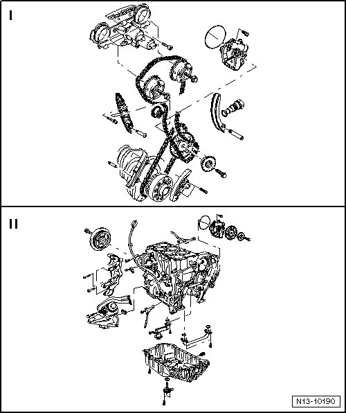
• The engine is to be secured to the engine and transmission holder (VAS 6095) when performing assembly work.
• If large quantities of metal particles or abraded material are detected during engine repairs, it may be an indication of a damaged crankshaft or rod bearings. To prevent further damage, perform the following steps after the repair:
• Carefully the clean oil passages.
• Replace the oil check valve.
• Replace the oil injection jets.
• Replace the oil cooler.
• Replace the oil filter.
Chain Drive Overview
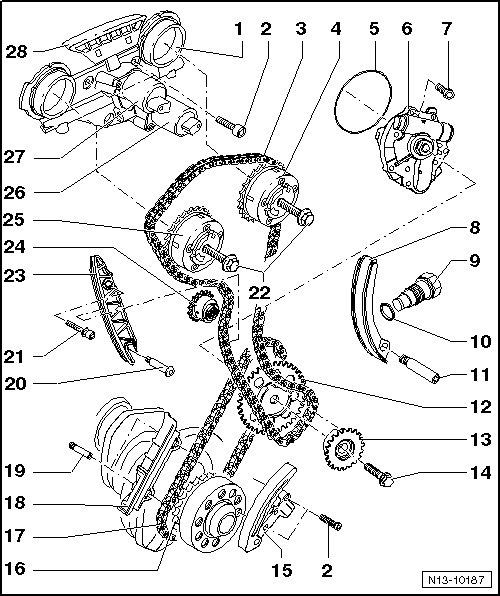
1 Control Housing
• Lubricate the contact surface of the seals before installing.
• Removing and installing, refer to => [ Camshafts ] Service and Repair.
• Camshaft adjustment valves, removing and installing. Refer to => [ Camshaft Adjuster Valves ] Camshaft Adjuster Valves.
• Check the control housing strainer for contamination before installing. Refer to => [ Checking Control Housing
Strainer for Contaminants ] Service and Repair.
2 Bolt
• 8 Nm
• Install using locking fluid (D 000 600 A2).
3 Camshaft Timing Chain
• Mark the direction of rotation before removing (installed position).
• Installing, refer to => [ Primary Chain, Installing ] Service and Repair.
4 Exhaust Camshaft Adjuster
• Identification: 32A
• Installing, refer to => [ Camshaft Adjuster with Timing Chain, Installing ] Camshaft Adjuster With Timing Chain, Installing.
5 Seal
• Replace
6 Oil Pump
• Removing and installing, refer to => [ Oil Pump ] Service and Repair.
7 Bolt
• 8 Nm
• Replace
8 Tensioning Rail
• For the camshaft timing chain - item 3 -.
9 Chain Tensioner
• 50 Nm
• For the camshaft timing chain - item 3 -.
• Only rotate the engine with the chain tensioner installed.
10 Seal
• Replace if damaged or leaking.
11 Pivot Pin
• 10 Nm
• For the tensioning rail - item 8 -.
12 Oil Pump Sprocket
• For the primary chain - item 17 -.
• Installing, refer to => [ Primary Chain, Installing ] Service and Repair.
13 Chain Sprocket
• For the camshaft timing chain - item 3 -.
• Installing, refer to => [ Primary Chain, Installing ] Service and Repair.
14 Bolt
• 60 Nm + 90° (1/4) additional turn.
• Replace
• Only use bolts with a strength category of 10.9.
15 Chain Tensioner with Tensioning Rail
• For the primary chain - item 17 -.
• Before installing, release the locking device in the chain tensioner with a small screwdriver and press the tensioning plate against the chain tensioner.
• Only rotate the engine with the chain tensioner installed.
16 Crankshaft Chain Sprocket
• Integral part of the crankshaft.
• Ground down tooth aligned with the main bearing joint = Top Dead Center (TDC) for cylinder 1 => [ Primary Chain, Installing ] Service and Repair.
17 Primary Chain
• Mark the direction of rotation before removing (install position).
• Installing, refer to => [ Primary Chain, Installing ] Service and Repair.
18 Guide Rail
• For the primary chain - item 17 -
• Remove and install together with the timing chain. Refer to => [ Primary Chain, Installing ] Service and Repair.
19 Locating Pin without Collar
• 10 Nm
• For the guide rail - item 18 -.
20 Pivot Pin
• 10 Nm
21 Bolt
• 23 Nm
22 Bolt
• 60 Nm + 90° (1/4) additional turn.
• Replace
• The sensor wheel contact surface on the bolt head must be dry when installing.
• When removing and installing, counter hold the camshaft with a 27 mm open end wrench, refer to => [ Camshafts ] Service and Repair.
23 Guide Rail
• For the camshaft timing chain - item 3 -.
24 Drive Chain Sprocket
• For the high pressure pump. Refer to => [ Fuel Rail, Injectors and High Pressure Pump Overview, through 07.07 ] One Piece Intake Manifold.
25 Intake Camshaft Adjuster
• Identification: 24E
• Installing, refer to => [ Camshaft Adjuster with Timing Chain, Installing ] Camshaft Adjuster With Timing Chain, Installing.
26 Camshaft Adjustment Valve 1 (Exhaust) (N318)
• For the exhaust camshaft.
• Mark the connector belonging to the component before disconnecting.
• Removing and installing, refer to => [ Camshaft Adjuster Valves ] Camshaft Adjuster Valves.
27 Camshaft Adjustment Valve 1 (N205)
• For the intake camshaft.
• Mark the connector belonging to the component before disconnecting.
• Removing and installing, refer to => [ Camshaft Adjuster Valves ] Camshaft Adjuster Valves.
28 Guide Rail
• For the camshaft timing chain - item 3 -.
• Clipped to the control housing.
Marking the Direction of the Camshaft Timing and Primary Chain
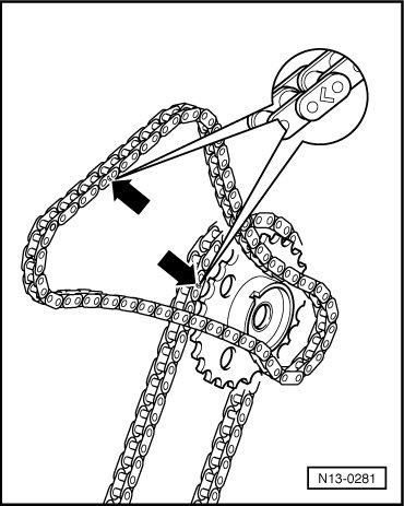
- Mark the timing and primary chains before removing (for example, with a arrow (paint) pointing in the direction of rotation).
• Do not mark the chain using a center punch or similar means!
Cylinder Block and Components Overview
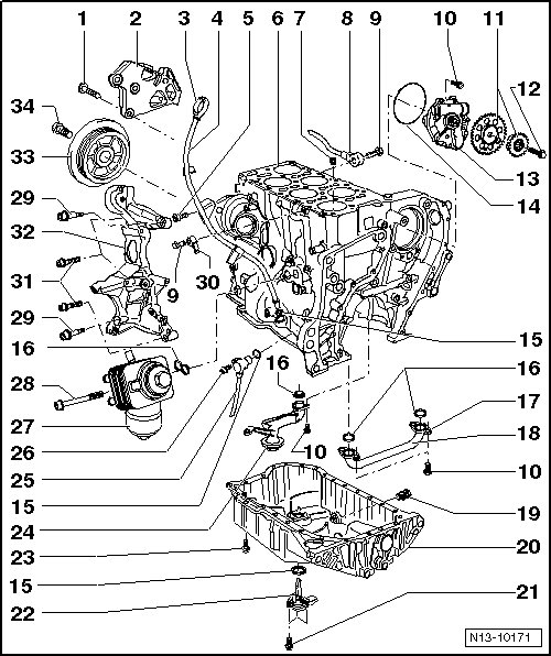
1 Bolt
• 50 Nm + 90° (1/4) additional turn.
• Replace
2 Engine Mount Bracket
3 Oil Dipstick
• Oil level must not be above the Max. mark!
• Marks, refer to => [ Engine Oil ] Description and Operation.
4 Oil Dipstick Guide Tube
• For the oil dipstick.
• Secured to the intake manifold by a bolt - item 5 -.
5 Bolt
• 6 Nm
• To the intake manifold.
6 Cylinder Block
• Sealing flange and drive plate overview. Refer to => [ Sealing Flange and Drive Plate Overview ] Sealing Flange and Drive Plate Overview.
• Crankshaft overview. Refer to => [ Crankshaft Overview ] Service and Repair.
• Piston and connecting rod overview. Refer to => [ Piston and Connecting Rod Overview ] Piston and Connecting Rod Overview.
7 Oil Check Valve
• Note the installed position.
• Clean if badly contaminated.
• See note.
• Removing and installing, refer to => [ Oil Check Valve, Removing
and Installing ] Oil Pan, Pump and Filter Housing Overview.
8 Knock Sensor (KS) 1 (G61)
• Installed location: between cylinders 1 and 3.
9 Bolt
• 20 Nm
• Tightening specification affects the function of the KS.
10 Bolt
• 8 Nm
• Replace
11 Oil Pump Sprocket
• Installing, refer to => [ Primary Chain, Installing ] Service and Repair.
12 Bolt
• 60 Nm + 90° (1/4) additional turn.
• Replace
• Only use bolts with a strength category of 10.9.
13 Oil Pump
• Removing and installing, refer to => [ Oil Pump ] Service and Repair.
14 Seal
• Replace
• Lubricate before assembling.
15 O-ring
• Replace
16 Gasket
• Replace
17 Oil Pipe Flange
• Note the installed position.
18 Oil Pipe
19 Oil Drain Plug
• 30 Nm
• Replace
• With a permanent seal.
20 Oil Pan
• Removing and installing, refer to => [ Oil Pan ] Service and Repair.
21 Bolt
• 10 Nm
22 Oil Level Thermal Sensor (G266)
23 Bolt
• 11 Nm
24 Suction Pipe
• For the oil pump.
25 Engine Speed (RPM) Sensor (G28)
26 Bolt
• 10 Nm
27 Oil Filter Housing
• Overview, refer to => [ Oil Filter Housing Overview ] Service and Repair.
28 Bolt
• 23 Nm
29 Bolt
• 23 Nm
30 Knock Sensor (KS) 2 (G66)
• Installed location: between cylinders 4 and 6.
31 Bolt
• 23 Nm
32 Accessory Bracket
• For the generator and Air Conditioning (A/C) compressor.
• Removing and installing, refer to => [ Accessory Bracket ] Service and Repair.
33 Vibration Damper
• Removing and installing, refer to => [ Vibration Damper ] Service and Repair.
• Removing and installing ribbed belt. Refer to => [ Ribbed Belt ] Ribbed Belt.
34 Bolt
• 100 Nm + 180° (1/2) additional turn.
• Replace
• Removing and installing, refer to => [ Vibration Damper ] Service and Repair.