Component Locations Overview
Component Locations Overview
Engine compartment, right
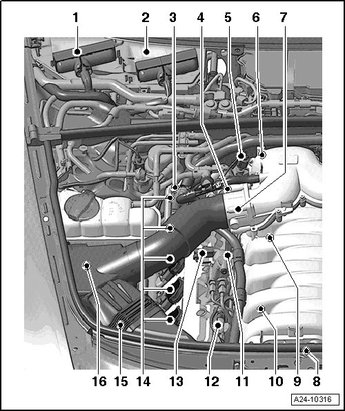
1 - Engine control module (ECM) 2 (J624)
• Component location => [ Engine control module installation locations ]
• Removing and installing, refer to => [ Engine Control Module 2, Slave ] Engine Control Module 2, Slave
2 - Engine Control Module (J623)
• Component location => [ Engine control module installation locations ]
• Removing and installing, refer to => [ Engine Control Module 1, Master ] Engine Control Module 1, Master
3 - Camshaft Adjustment Valve 1 (exhaust) (N318)
• Component location => [ Location on right cylinder bank 1 ]
4 - Camshaft Adjustment Valve 1 (N205)
• Component location => [ Location on right cylinder bank 1 ]
5 - Low Fuel Pressure Sensor (G410)
• Component location => [ Engine from behind ]
6 - Engine Coolant Temperature (ECT) Sensor (G62)
• Component location => [ Engine from behind ]
7 - Throttle valve control module (J338)
• After replacing, adapt in "Guided Functions" operating mode under "Adapting throttle valve control module"
8 - Components on front of engine
• => [ Engine viewed from front ]
• Intake Manifold Runner Position Sensor (G336)
• Variable Intake Manifold Runner Motor (V183)
• Intake Flap Motor (V157)
• Secondary air injection (AIR) solenoid valve (N112)
• Intake Manifold Runner Position Sensor 2 (G512)
• Oil pressure switch (F1)
• Knock Sensor (KS) 4 (G199)
• Knock Sensor (KS) 3 (G198)
• Knock Sensor (KS) 1 (G61)
• Knock Sensor (KS) 2 (G66)
9 - Knock Sensor (KS) 2 (G66)
• Component location => [ Location inside cylinder head ]
• Electrical harness connector => [ Engine viewed from front ]
• 22 Nm
10 - Knock Sensor (KS) 1 (G61)
• Component location => [ Location inside cylinder head ]
• Electrical harness connector => [ Engine viewed from front ]
• 22 Nm
11 - High pressure pump
• With Fuel Metering Valve (N290)
12 - Camshaft Position (CMP) sensor (G40)
• Component location => [ Location on right cylinder bank 1 ]
13 - Fuel Metering Valve (N290) electrical connector
• Common component with high pressure pump
14 - Ignition coils, Cylinder bank 1
• Ignition Coil 1 with Power Output Stage (N70)
• Ignition Coil 2 with Power Output Stage (N127)
• Ignition Coil 3 with Power Output Stage (N291)
• Ignition Coil 4 with Power Output Stage (N292)
• Removing and installing, refer to => [ Ignition Coils with Power Output Stages ] Service and Repair
15 - Camshaft position (CMP) sensor 3 (G300)
• Component location => [ Location on right cylinder bank 1 ]
16 - Mass Air Flow (MAF) Sensor (G70)/Intake Air Temperature (IAT) Sensor (G42)
• Removing and installing, refer to => [ Bank 1 Mass Air Flow Sensor ] Bank 1 Mass Air Flow Sensor
• installed in air filter housing
Engine compartment, left
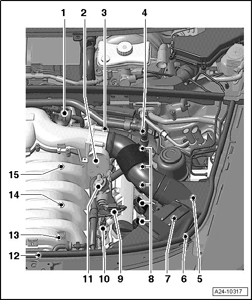
1 - Evaporative Emission (EVAP) Canister Purge Regulator Valve (N80)
• => [ Installation Locations ]
2 - Throttle Valve Control Module 2 (J544)
• After replacing, adapt in "Guided Functions" operating mode under "Adapting throttle valve control module"
3 - Camshaft Adjustment Valve 2 (N208)
• Component location => [ Location on left cylinder bank 2 ]
4 - Camshaft Adjustment Valve 2 (exhaust) (N319)
• Component location => [ Location on left cylinder bank 2 ]
5 - Mass Air Flow (MAF) Sensor 2 (G246)
• Removing and installing, refer to => [ Bank 2 Mass Air Flow Sensor ] Bank 2 Mass Air Flow Sensor
• Installed in air filter housing
6 - Secondary Air Injection (AIR) Pump Motor (V101)
• Below left long member
• Component location => [ (below left long member) ]
7 - Camshaft position (CMP) sensor 4 (G301)
• attached to outside of cylinder head
• Component location => [ Location on left cylinder bank 2 ]
8 - Ignition coils, Cylinder bank 2
• Ignition Coil 5 with Power Output Stage (N323)
• Ignition Coil 6 with Power Output Stage (N324)
• Ignition Coil 7 with Power Output Stage (N325)
• Ignition Coil 8 with Power Output Stage (N326)
• Removing and installing, refer to => [ Ignition Coils with Power Output Stages ] Service and Repair
9 - Fuel Metering Valve 2 (N402) electrical connector
• Common component with high pressure pump
10 - Camshaft position (CMP) sensor 2 (G163)
• Component location => [ Location on left cylinder bank 2 ]
11 - High pressure pump
• With Fuel Metering Valve 2 (N402)
12 - Components on front of engine
• => [ Engine viewed from front ]
• Intake Manifold Runner Position Sensor (G336)
• Variable Intake Manifold Runner Motor (V183)
• Intake Flap Motor (V157)
• Secondary air injection (AIR) solenoid valve (N112)
• Intake Manifold Runner Position Sensor 2 (G512)
• Oil pressure switch (F1)
• Knock Sensor (KS) 4 (G199)
• Knock Sensor (KS) 3 (G198)
• Knock Sensor (KS) 1 (G61)
• Knock Sensor (KS) 2 (G66)
13 - Fuel Pressure Sensor (G247)
• Component location => [ Location inside cylinder head ]
14 - Knock Sensor (KS) 3 (G198)
• Component location => [ Location inside cylinder head ]
• Electrical harness connector => [ Engine viewed from front ]
• 22 Nm
15 - Knock Sensor (KS) 4 (G199)
• Component location => [ Location inside cylinder head ]
• Electrical harness connector => [ Engine viewed from front ]
• 22 Nm
A - Engine speed (RPM) sensor (G28)
• => [ ]
B - Throttle Position (TP) Sensor (G79)/Accelerator Pedal Position Sensor 2 (G185)
• => [ Component location / ]
C - Brake light switch (F)/Brake pedal switch (F47)
• => [ Component location /, and ]
D - Clutch Pedal Switch (F36) and Clutch Position Sensor (G476)
• => [ Component location /, and ]
E - Heated Oxygen Sensor (HO2S) (G39) before catalytic converter with Oxygen Sensor (O2S) Heater (Z19)
• Exhaust bank I (cylinder 1, 2, 3)
• Location of electrical connector
• Removing and installing, refer to => [ Heated Oxygen Sensors before Catalytic Converter ] Heated Oxygen Sensors before Catalytic Converter
F - Heated Oxygen Sensor (HO2S) 2 (G108) before catalytic converter with Oxygen Sensor (O2S) 2 Heater (Z28)
• Exhaust bank II (cylinder 4, 5)
• Location of electrical connector => [ Location of electrical connectors for oxygen
sensors , , , , , ] Oxygen Sensors Assembly Overview
• Removing and installing, refer to => [ Heated Oxygen Sensors before Catalytic Converter ] Heated Oxygen Sensors before Catalytic Converter
G - Heated Oxygen Sensor (HO2S) 3 (G285) before catalytic converter with Oxygen Sensor (O2S) 3 Heater (Z62)
• Exhaust bank III (cylinder 6, 7, 8)
• Location of electrical connector => [ Location of electrical connectors for oxygen
sensors and ] Oxygen Sensors Assembly Overview
• Removing and installing, refer to => [ Heated Oxygen Sensors before Catalytic Converter ] Heated Oxygen Sensors before Catalytic Converter
H - Heated Oxygen Sensor (HO2S) 4 (G286) before catalytic converter with Oxygen Sensor (O2S) 4 Heater (Z63)
• Exhaust bank IV (cylinder 9, 10)
• Location of electrical connector => [ Location of electrical connectors for oxygen
sensors , , , , , ] Oxygen Sensors Assembly Overview
• Removing and installing, refer to => [ Heated Oxygen Sensors before Catalytic Converter ] Heated Oxygen Sensors before Catalytic Converter
I - Oxygen Sensor (O2S) Behind Three Way Catalytic Converter (TWC) (G130) with Oxygen Sensor (O2S) 1 (behind Three Way Catalytic Converter (TWC)) Heater (Z29)
• Exhaust bank I (cylinder 1, 2, 3)
• Location of electrical connector => [ Location of electrical connectors for oxygen
sensors , , , , , ] Oxygen Sensors Assembly Overview
• Removing and installing, refer to => [ Heated Oxygen Sensors before Catalytic Converter ] Heated Oxygen Sensors before Catalytic Converter
J - Oxygen Sensor (O2S) 2 Behind Three Way Catalytic Converter (TWC) (G131) with Oxygen Sensor (O2S) 2 (behind Three Way Catalytic Converter (TWC)) Heater (Z30)
• Exhaust bank II (cylinder 4, 5)
• Location of electrical connector => [ Location of electrical connectors for oxygen
sensors , , , , , ] Oxygen Sensors Assembly Overview
• Removing and installing, refer to => [ Heated Oxygen Sensors before Catalytic Converter ] Heated Oxygen Sensors before Catalytic Converter
K - Oxygen Sensor (O2S) 3 Behind Three Way Catalytic Converter (TWC) (G287) with Oxygen Sensor (O2S) 3 (behind Three Way Catalytic Converter (TWC)) Heater (Z64)
• Exhaust bank III (cylinder 6, 7, 8)
• Location of electrical connector => [ Location of electrical connectors for oxygen
sensors , , , , , ] Oxygen Sensors Assembly Overview
• Removing and installing, refer to => [ Heated Oxygen Sensors before Catalytic Converter ] Heated Oxygen Sensors before Catalytic Converter
L - Oxygen Sensor (O2S) 4 Behind Three Way Catalytic Converter (TWC) (G288) with Oxygen Sensor (O2S) 4 (behind Three Way Catalytic Converter (TWC)) Heater (Z65)
• Exhaust bank IV (cylinder 9, 10)
• Location of electrical connector => [ Location of electrical connectors for oxygen
sensors , , , , , ] Oxygen Sensors Assembly Overview
• Removing and installing, refer to => [ Heated Oxygen Sensors before Catalytic Converter ] Heated Oxygen Sensors before Catalytic Converter
Engine control module installation locations
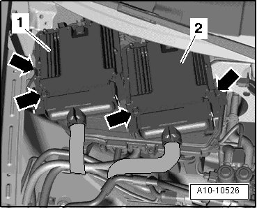
1 Shows Engine Control Module (ECM) 2 (J624) (slave)
2 Shows Engine Control Module (ECM) (J623) (master)
Component location Throttle Position (TP) Sensor (G79)/Sender 2 for accelerator pedal position (G185)
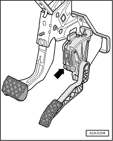
• In accelerator pedal module - arrow -.
• The Throttle Position (TP) Sensor (G79) and Accelerator Pedal Position Sensor 2 (G185) are integrated into the accelerator pedal module and cannot be replaced separately.
Component location Brake Light Switch (F)/Brake Pedal Switch (F47), Clutch Pedal Switch (F36) and Clutch Position Sensor (G476)
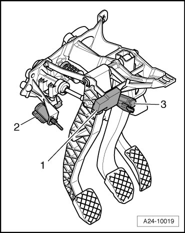
• On pedal bracket.
1. Clutch Position Sensor (G476)
2. Clutch pedal switch (F36)
3. Brake light switch (F)/Brake pedal switch (F47)
Installation Locations
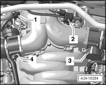
1 Low Fuel Pressure Sensor (G410)
2 Evaporative Emission (EVAP) Canister Purge Regulator Valve (N80)
3 Throttle Valve Control Module 2 (J544)
4 Throttle valve control module (J338)
Perform an "adaptation" after replacing the throttle valve control module, see "Guided Functions" in Vehicle Diagnosis, Testing and Information System (VAS 5051B).
Engine from behind
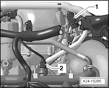
1 Low Fuel Pressure Sensor (G410)
2 Engine Coolant Temperature (ECT) Sensor (G62), removing and installing.
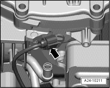
Engine Speed (RPM) Sensor (G28) - arrow -
Engine viewed from front
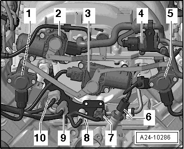
1 Intake Manifold Runner Position Sensor (G336)
2 Variable Intake Manifold Runner Motor (V183)
3 Intake Flap Motor (V157)
4 Secondary air injection (AIR) solenoid valve (N112)
5 Intake Manifold Runner Position Sensor 2 (G512)
6 Oil Pressure Switch (F1)
7 Knock sensor 4 (G199) (blue connector)
8 Knock Sensor 3 (G198) (white connector)
9 Knock Sensor (KS) 1 (G61) (orange connector)
10 Knock Sensor (KS) 2 (G66) (gray connector)
• Intake manifold must be removed in order to remove knock sensors. Intake manifold, removing and installing. Refer to => [ Intake Manifold ] Intake Manifold.
Location inside cylinder head
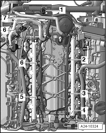
1 Engine Coolant Temperature (ECT) Sensor (G62)
2 Knock Sensor (KS) 4 (G199)
3 Knock Sensor (KS) 3 (G198)
4 Fuel Pressure Sensor (G247)
5 Knock Sensor (KS) 1 (G61)
6 Knock Sensor (KS) 2 (G66)
7 Camshaft Adjustment Valve 1 (N205)
8 Low Fuel Pressure Sensor (G410)
• Intake manifold must be removed to remove Fuel Pressure Sensor (G247) or knock sensors. Refer to => [ Intake Manifold ] Intake Manifold.
Location on right cylinder bank 1
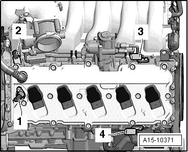
1 Camshaft Adjustment Valve 1 (exhaust) (N318)
2 Camshaft Adjustment Valve 1 (N205)
3 Camshaft Position (CMP) sensor (G40)
4 Camshaft position (CMP) sensor 3 (G300)
Location on left cylinder bank 2
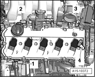
1 Camshaft position (CMP) sensor 4 (G301)
2 Camshaft position (CMP) sensor 2 (G163)
3 Camshaft Adjustment Valve 2 (N208)
4 Camshaft Adjustment Valve 2 (exhaust) (N319)
Oxygen sensor electrical connectors (on vehicle floor)
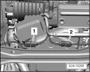
1 Heated Oxygen Sensor (HO2S) (G39) (in front of catalytic converter) black connection
2 Heated Oxygen Sensor (HO2S) 3 (G285) (in front of catalytic converter) brown connector
Oxygen sensor electrical connectors (at top of transmission)
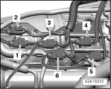
1 Gray Oxygen Sensor (O2S) 4 Behind Three Way Catalytic Converter (TWC) (G288)
2 Black Oxygen Sensor (O2S) 3 Behind Three Way Catalytic Converter (TWC) (G287)
3 Brown Oxygen Sensor (O2S) Behind Three Way Catalytic Converter (TWC) (G130)
4 Brown Heated Oxygen Sensor (HO2S) 4 (G286) (in front of catalytic converter)
5 Black Heated Oxygen Sensor (HO2S) 2 (G108) (in front of catalytic converter)
6 Black Oxygen Sensor (O2S) 2 Behind Three Way Catalytic Converter (TWC) (G131)
Secondary Air Injection (AIR) Pump Motor (V101) (below left long member)
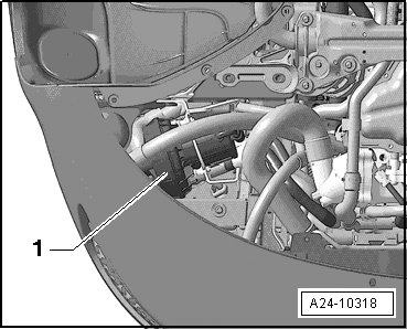
• Removing and installing.