Fuel Pump Control Module, FSI, Checking
Fuel Pump Control Module, FSI, Checking
Special tools, testers and auxiliary items required
• Hand-held multimeter (V.A.G 1526C)
• Connector test set (V.A.G 1594C)
• Adapter cable (V.A.G 1598/39)
• Test box (V.A.G 1598/42)
Procedure
Observe test conditions. Refer to => [ Test Conditions ] Test Conditions.
Check voltage supply for Fuel Pump (FP) (from Fuel Pump (FP) Control Module (J538))
- Remove rear seat bench.
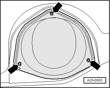
- Unbolt cover for right locking flange - arrows -.
- For voltage testing, connect the (V.A.G 1526C) with measuring probes and connector adapters from the (V.A.G 1594C) between clamp - 1 - and - 5 -, as shown in the illustration. The electrical connection remains connected.
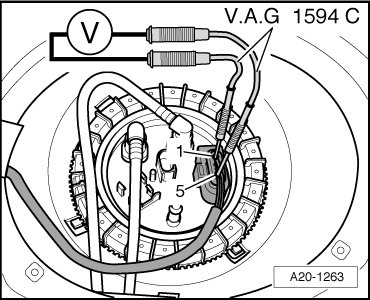
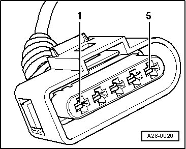
• Connector sockets are numbered respectively on the rear side of the connector.
- Start engine.
• Specified value at start and in idle: 4 to 5 V.
- Depress accelerator pedal completely and then release it (brief throttle burst).
• Specified value: The voltage value must first rise slightly, then fall and then rise again to the value previously read.
If the reading does not result as described:
- Check voltage supply and activation of the Fuel Pump (FP) Control Module.
Check voltage supply for Fuel Pump (FP) Control Module
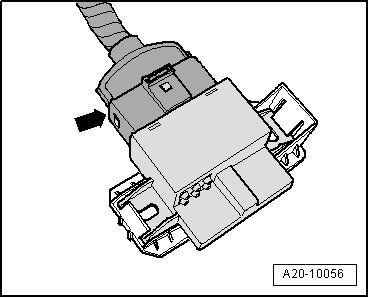
- Remove fuel pump (FP) control module. Refer to => [ Fuel Pump Control Module ] Fuel Pump Control Module.
- Disconnect electrical harness connector - arrow - on fuel pump (FP) control module.
- Connect multimeter between terminal - 3 - and - 4 - of harness connector for voltage measurement.
- Switch on ignition.
• Specified value: approximately battery voltage.
If the specification is not obtained:
- Repair open circuit in wiring according to wiring diagram.
Check activation of Fuel Pump (FP) Control Module
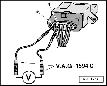
- Remove protective cap.
- For voltage testing, connect the multimeter with measuring probes and connector adapters from the (V.A.G 1594C) between clamp - 4 - and - 5 -, as shown in the illustration. The electrical connection remains connected.
• Connector sockets are numbered respectively on the rear side of the connector.
- Start engine.
• Specified value at start and in idle: approximately 5.0 V
- Depress accelerator pedal completely and then release it (brief throttle burst).
• Specified value: The voltage value must first rise slightly, then fall and then rise again to the value previously read.
If the reading does not result as described:
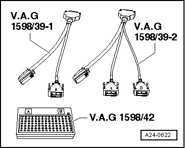
- Switch off ignition.
- Connect (V.A.G 1598/42) to wiring harness with (V.A.G 1598/39-1) or (V.A.G 1598/39-2); engine control module (ECM) is not connected. Clamp test box ground (GND) clip to battery negative terminal.
CAUTION!
Risk of destroying electrical components.
• Before connecting the test leads, switch on the respective measuring range and observe the test conditions.
- Check the following wire connection for open circuit and short circuit to ground (GND) and B+:

- Repair wiring open circuit or short circuit according to wiring diagram.
If no malfunctions are detected:
- Replace the fuel pump (FP) control module. Refer to => [ Fuel Pump Control Module ] Fuel Pump Control Module.