Component Location Overview
Component Location Overview
Components A through P are not shown in the illustration.
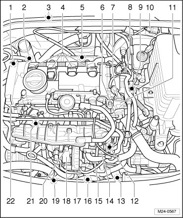
1 - Wastegate Bypass Regulator Valve (N75)
• Installed directly on the turbocharger, refer to => [ Components on the Turbocharger ].
2 - Turbocharger Recirculating Valve (N249)
• Installed directly on the turbocharger, refer to => [ Components on the Turbocharger ].
3 - Motronic Engine Control Module (J220)
• Removing and installing, refer to one of the following:
• => [ Engine Control Module, without Anti-Theft Protection ] Engine Control Module, without Anti-Theft Protection.
• => [ Engine Control Module, with Anti-Theft Protection ] Engine Control Module, with Anti-Theft Protection.
4 - Ignition Coils with Power Output Stages
• Removing and installing, refer to => [ Ignition Coils with Power Output Stages ] Service and Repair.
• Ignition coils must be pull out of the cylinder head using the ignition coil puller (T40039).
5 - Heated Oxygen Sensor (HO2S) (G39) and Oxygen Sensor (O2S) Heater (Z19)
6 - Low Fuel Pressure Sensor (G410)
7 - Fuel Pressure Regulator Valve (N276)
8 - Camshaft Adjustment Valve 1 (N205)
• Removing and installing, refer to => [ Camshaft Adjustment Valve 1 ] Camshaft Adjustment Valve 1.
9 - Engine Coolant Temperature (ECT) Sensor (G62)
• Refer to => [ Engine Coolant Temperature (ECT) Sensor ].
10 - 6 Pin Connector
• For the HO2S and O2S heater (black). Refer to => [ Harness Connector for the HO2S and O2S Heater ].
11 - Single Piston High Pressure Pump
• Removing and installing, refer to => [ High Pressure Pump ] High Pressure Pump.
12 - Intake Flap Motor (V157) with Intake Manifold Runner Position Sensor (G336)
• After replacing the fuel rail, the intake manifold runner position sensor must be adapted again to the Motronic ECM. Refer to => vehicle diagnosis, testing and information system (VAS 5051).
13 - Engine Speed (RPM) Sensor (G28)
• Refer to => [ Connectors ].
14 - Evaporative Emission (EVAP) Canister Purge Regulator Valve 1 (N80)
15 - Connector
• For the Camshaft Position (CMP) sensor and fuel pressure sensor.
• Refer to => [ Component Locations Beneath Intake Manifold ].
16 - Charge Air Pressure Sensor (G31)
• Refer to => [ Charge Air Pressure Sensor ].
17 - 8 Pin Harness Connector for Fuel Injectors
• Refer to => [ Component Locations Beneath Intake Manifold ].
18 - Throttle Valve Control Module (J338), Throttle Drive (for Electronic Power Control (EPC)) (G186)
• Throttle drive angle sensor 1 (for Electronic Power Control (EPC)) and throttle drive angle sensor 2 (for EPC).
• During replacement, erase the adaptation values and adapt the ECM to the throttle valve control module. Refer to => vehicle diagnosis, testing and information system (VAS 5051).
19 - Engine Coolant Temperature (ECT) Sensor (on Radiator) (G83)
• Refer to => [ Engine Coolant Temperature (ECT) Sensor (on
Radiator) ].
20 - Intake Air Temperature (IAT) Sensor (G42)
21 - Fuel Pressure Sensor (G247)
• Refer to => [ Fuel Pressure Sensor ].
22 - Camshaft Position (CMP) Sensor (G40)
• Connector, refer to => [ Camshaft Position (CMP) Sensor ].
A - Data Link Connector (DLC)
• In the driver's foot well.
B - Mass Air Flow (MAF) Sensor (G70)
• In the upper section of the air filter housing, refer to => [ Mass Air Flow (MAF) Sensor ].
C - "EPC" Indicator Lamp
• In the instrument cluster.
D - Exhaust Malfunction Indicator Lamp "MIL"
• in the instrument cluster.
E - Oxygen Sensor (O2S) behind Three Way Catalytic Converter (TWC) (G130) and Oxygen Sensor (O2S) Heater 1 (behind Three Way Catalytic Converter (TWC)) (Z29)
• Refer to => [ O2S Behind TWC ].
• Connector, refer to => [ Harness Connector for O2S Behind TWC and O2S
Heater 1 Behind TWC on the Right Side Vehicle Floor ].
F - Brake Light Switch (F) and Brake Pedal Switch (F47)
• Refer to => [ Brake Light Switch and Brake Pedal Switch ].
G - Accelerator Pedal Module
• Throttle Position (TP) sensor with accelerator pedal position sensor 2.
• On the accelerator pedal module (both sensors are integrated into one housing).
• Refer to => [ Accelerator Pedal Module ].
H - Clutch Position Sensor (G476)
• Refer to => [ Harness Connector for Clutch Position Sensor ].
I - Relay and Fuse Carrier in E-box
• Refer to => [ Relay and Fuse Carrier in E-box ].
J - Coolant Fan Control (FC) Control Module (J293)
• Installed on left fan (in direction of vehicle travel).
K - Fuel Injector
• In the fuel rail.
• Removing and installing, refer to => [ Fuel Injectors ] Fuel Injectors.
• Cylinder 1 fuel injector (N30)
• Cylinder 2 fuel injector (N31)
• Cylinder 3 fuel injector (N32)
• Cylinder 4 fuel injector (N33)
Fuel injectors referred to here are high pressure fuel injectors. They inject fuel directly into the cylinder under high pressure (Max. approximately 120 bar).
L - 3 Pin Harness Connector for Knock Sensor (KS) 1 (G61)
• Refer to => [ Connectors ].
M - 3 Pin Harness Connector for Knock Sensor (KS) 2 (G66)
• Refer to => [ Connectors ].
N - Knock Sensor (KS) 1 (G61)
• For cylinders 1 and 2.
• Tightening specification affect function of KS.
• Refer to => [ Component Locations Beneath Intake Manifold ].
O - Knock Sensor (KS) 2 (G66)
• For cylinders 3 and 4.
• Tightening specification affect function of KS.
• Refer to => [ Component Locations Beneath Intake Manifold ].
P - Oil Pressure Switch (F1)
• Refer to => [ Connectors ].
Engine Coolant Temperature (ECT) Sensor
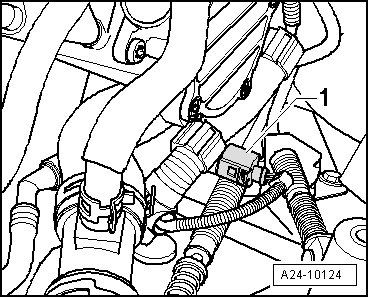
• ECT sensor - 1 -.
Fuel Pressure Sensor
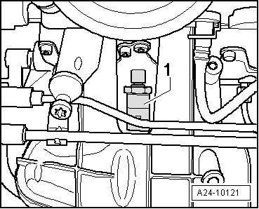
• Fuel pressure sensor - 1 -.
Camshaft Position (CMP) Sensor
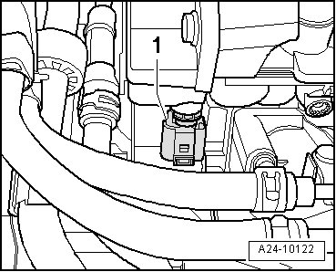
• CMP sensor - 1 -.
Mass Air Flow (MAF) Sensor
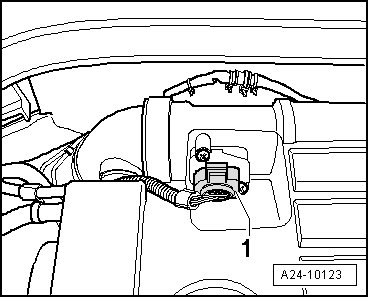
• MAF sensor - 1 -.
Harness Connector for the HO2S and O2S Heater
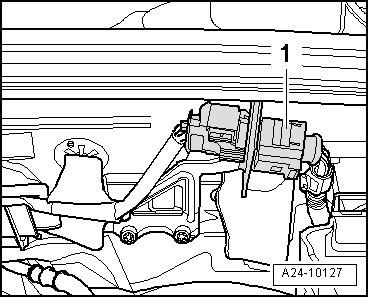
• Harness connector - 1 - for the HO2S and O2S heater.
O2S Behind TWC
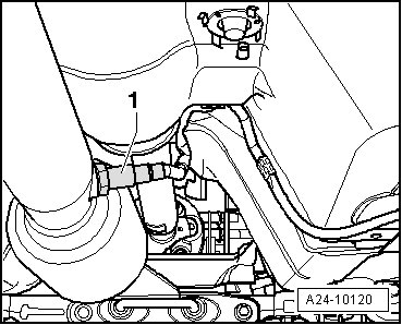
• O2S behind TWC - 1 - and O2S heater 1 behind TWC
Harness Connector for O2S Behind TWC and O2S Heater 1 Behind TWC on the Right Side Vehicle Floor
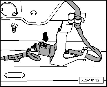
• Harness connector - arrow - for O2S behind TWC and O2S heater 1 behind TWC on the right side vehicle floor.
Engine Coolant Temperature (ECT) Sensor (on Radiator)
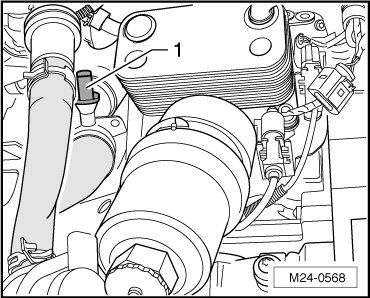
• ECT sensor (on radiator), - 1 - in front of coolant thermostat housing.
Harness Connector for Clutch Position Sensor
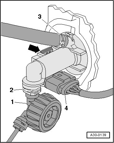
• Harness connector - 4 - for clutch position sensor.
Brake Light Switch and Brake Pedal Switch
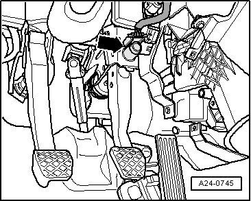
• Brake light switch and brake pedal switch - arrow -.
Accelerator Pedal Module
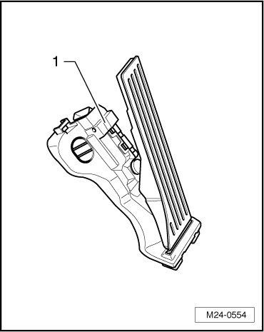
• Accelerator pedal module - 1 -.
• Throttle position sensor with accelerator pedal position sensor 2 (in the driver side footwell).
• On accelerator pedal module (both sensors are integrated into one housing).
Relay and Fuse Carrier in E-box
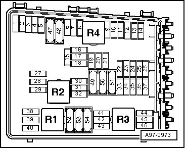
Relay and fuse assignment, refer to.
Connectors
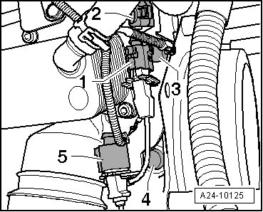
1. Green, 3 pin harness connector for the KS 1
2. Brown, 3 pin harness connector for the KS 2
3. Oil pressure switch
4. Engine speed (RPM) sensor
5. Gray, 3 pin harness connector for the engine speed (RPM) sensor
Component Locations Beneath Intake Manifold
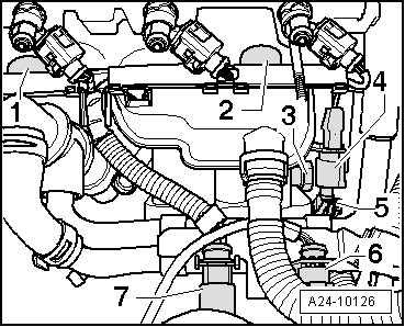
1. KS 1
2. KS 2
3. Oil pressure switch
4. Brown, 3 pin harness connector for the KS 2
5. Gray, 3 pin harness connector for the engine speed (RPM) sensor
6. Connector for the CMP sensor and fuel pressure sensor
7. 8 pin harness connector for fuel injectors
Charge Air Pressure Sensor
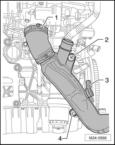
• Charge air pressure sensor - 3 -
Components on the Turbocharger
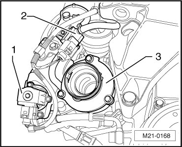
1. Tighten the turbocharger recirculating valve bolts to 7 Nm. Note the installed position, refer to => [ Turbocharger Recirculating Valve Installed
Position ].
2. Tighten the wastegate bypass regulator valve bolts to 3 Nm.
3. Turbocharger removing and installing, refer to => [ Turbocharger ] Turbocharger.
Turbocharger Recirculating Valve Installed Position
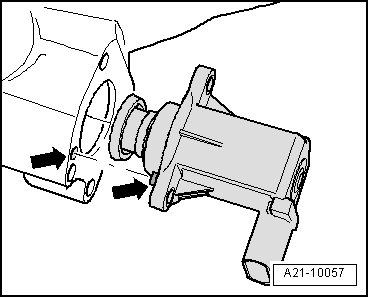
• Note the installed position - arrows - of the turbocharger recirculating valve